linear power supply PCB design,do you know?
Power supply circuit is an important part of an electronic product, powe module power supply circuit design is good or bad, directly affected the performance of the product is good or not.
The classification of the power supply circuit
Our electronic products power supply circuit mainly have the linear power supplies and high frequency switching power supply. In theory, linear power supply is that the resident involve how much current, how many current input will provide; Switching power supply is how much power you need, then offer how much power input end.
The example of linear power supply circuit principle diagram
Linear power supply power devices working in linear state, such as our commonly used LM7805 voltage chip, LM317, SPX1117, etc. Figure 1 is LM7805 regulated power supply circuit principle diagram.
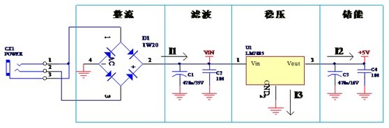
Figure 1. The principle diagram of the linear power supply
Known from the figure, the linear power made of rectifier, filter, voltage stability, energy storage, and other functions of components, meanwhile, the general use linear power supply is in series regulated power supply, the output current is equal to the input current, I1 = I2 + I3, I3 refers to the end, current is quite low, so the I1 material I3. Why do we speak of current, because the PCB design, the width of each line is uneasy to set, have to according to the principle diagram between the element node in the current size to determine (please check the PCB design thickness of copper, platinum, line width, and current relation table of). Current size, the current flow to be clear, do the plate to the right.
Linear power supply PCB figure
When donging PCB design, the layout of the components have to compact, and let all attachment line as short as possible, according to the principle of figure element to layout components and linear function relationship. Figure in this power supply is done by following steps rectifier, filter, filter again before they are after is the voltage regulator, voltage regulator is the energy storage capacitor, after flowing through the capacitor to the back of the power circuit.
Figure 2 is the schematic diagram of PCB diagram, two figures is similar. A little difference at left and right figure, the power of the left after rectification directly to the input voltage chips feet, and then the voltage regulator capacitor, the effect of filter output also has a problem. The picture on the right is the good figure. We should not only consider the power flow problem, must also consider the reflow problems, general speaking, the power cord with ground return in and out as close as possible, get close to each other
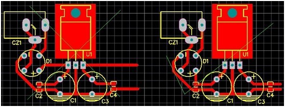
Figure 2. The PCB design of the linear power supply
Should also pay attention to the linear power supply PCB design, the power voltage chip heat dissipation problem, how does heat comes, if the ex-voltage regulator chip voltage is 10 v, output is 5 v, output current is 500 ma, there is 5V voltage drop on the voltage regulator chip, the generated heat is 2.5 W; If the input voltage is 15 v, voltage drop is 10 v, heat for 5 w, as a result, we are cloth plate according to heat power to set aside enough heat dissipation space or reasonable heat sink. Linear power supply generally used in pressure difference is small, current is low, otherwise, please switch to switching power supply circuit.