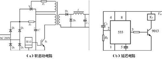
Dc dc switching power supply "soft start" circuit diagram. Shown in the following figure (a) During the electricity connection moment, input voltage would charge for capacitor C trough the rectifier bridge (from D1 to D4) and current limiting resistor R1, limiting surge current.
When the charging capacitor C to about 80% of the rated voltage, the inverter work normally. The main transformer secondary winding of thyristor trigger signal, causing the thyristor conduction and short circuit current limiting resistor R1, switch power supply work normally.
In order to improve the accuracy of delay time, prevent relay operation, delay circuit can use figure (b) instead the RC delay circuit.
Any questions about the circuts problem welcome to discuss with our R&D department.