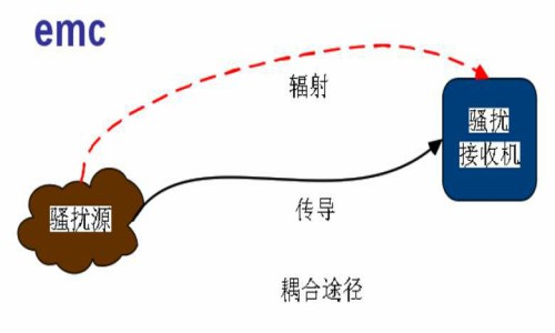
We have received some clients discuss the EMC with our engineer, after do lots of research and get to know there are two ways to prevent the interference for EMC solutions.
1# Grounding
1# Grounding
Before elucidating grounding, must master the basic concepts of grounding and change, protective grounding, and protective zero. That is, the ground wire refers to the metal connecting wire that connects the earth to the earth, and the neutral wire is the working wire provided by the power department in China; the protective grounding is to connect the metal shell of the instrument and equipment to the ground wire and cause the shell to be charged due to interference.
Currents flow into the earth along the ground, achieving the purpose of protecting the safety of people and equipment. The protection zero is to connect the metal shell of the instrument and equipment to the zero line of the power supply. In the event of a short circuit, the fuse is blown to cut off the power supply immediately.
2# Signal Grounding Of Equipment
1. Floatly insulates the “zero” potential of the circuit or the “zero” potential of the device from the common grounding system or the common conductor that may cause circulation, OR it is not grounded, making this “zero” potential relative to the earth is a Floating "zero" potential. Commonly used transformer isolation and optocoupler isolation. The advantage of floating ground is strong anti-interference ability, the disadvantage is static electricity accumulation. When the charge accumulates to a certain extent, the potential difference between the equipment ground and the public ground may cause severe electrostatic discharge, and become a destructive source of harassment. The solution is to bridge the discharge resistance between the floating ground and the public ground, and the size of the resistance should be suitable so as not to affect the leakage current of the equipment.
2. Single-point grounding circuits and equipment Where a point that needs to be grounded, is connected to a point at which only one physical point is defined as single-point ground. Using single-point grounding for a system , each device must have its own single point of ground, and then the ground of each device is connected to the only designated reference ground point in the system. The disadvantage is that the system has a certain reactance effect when the operating frequency is high, causing poor grounding effect.
3. Multi-point grounding refers to the points in the equipment that need to be grounded and all are directly connected to the closest grounding plane. The advantage is simple, high frequency standing wave is small. The disadvantage is the large amount of maintenance.
4. The mixed ground sets the length of single-point and multi-point grounding, connects the nearby grounding point, and connects directly to the grounding plane or the point that needs high-frequency grounding. It is connected to the grounding plane through the bypass capacitor. The rest of the points are all single grounding. When the circulating signal wavelength is lower than 0.05λ, single-point grounding is workable. When the length of the grounding line is longer than 0.05λ, multi-point grounding should be used.
Hope this article is useful to you.